Refactoring RPLidar S3 Driver: When Ideal Abstractions Meet Hardware Reality (Part 3)
Abstraction is beautiful until you plug in the USB cable. How to design a unified driver architecture for fragmented hardware lineups (A1, S3, C1) using Factory Patterns and Finite State Machines.
Introduction: The Illusion of “Clean Code”
“In Part 2, our Object-Oriented design was flawless. Until we turned on the power.”
In the previous post, we dreamed of perfect Polymorphism and Dependency Injection. In the IDE, every LiDAR was an abstract object that obediently rotated when start() was called and returned point clouds via scan().
However, the moment I connected the USB cable, that peace was shattered.
Part 3 discusses how “Ideal Abstractions” collide with “Physical Constraints,” and how the code must evolve to survive the harsh reality of hardware fragmentation. We move from architectural theory to the messy trenches of serial protocols and timing latencies.
1. The Compatibility Trap: Hardware Fragmentation
The first wall I hit was the sheer chaos of the manufacturer’s lineup. The legacy code was riddled with if (model == A1) statements—a classic “Switch Statement Smell.”
Initially, I scoffed, thinking a simple Interface would solve it. I was wrong. The product lineup was not just a list; it was a tangled web of legacy and modern architectures.
- A-Series (The Legacy): A1, A2, A3. Reliable veterans using the classic protocol (
Standard/Express). Old, but standard. - S-Series (The Flagship): S1, S2, S3. The new generation using high-speed protocols (
HQ Scan) for TOF performance. - C-Series (The Hybrid Trap): This is the anomaly. The C1 is an entry-level model (similar specs to A1) but uses the S-series’ high-speed protocol internally.
The equation “Low Cost = Legacy Protocol” was false. We had to decouple Performance Specs from Communication Protocols. My initial assumption that “All LiDARs are created equal” was a naive oversimplification.
2. Documentation Recon: The Archaeology of Protocols
“Before writing a single line of code, I had to become an archaeologist.”
If Part 1 was about the “How” (Legacy Code), Part 2 starts with the “Where” (Datasheets). There was no “Single Source of Truth.” Instead, the information was scattered across multiple disjointed documents hidden in different corners of the vendor’s website.
I had to cross-reference three different protocol versions just to understand the landscape:
LR001_SLAMTEC_rplidar_protocol_v2.4_en.pdf(The Legacy Bible)LR001_SLAMTEC_rplidar_S series_protocol_v1.0_en.pdf(The High-Speed Variant)LR001_SLAMTEC_rplidar_S&C series_protocol_v2.8_en.pdf(The Modern Hybrid)
The problem was “Information Silos.” The A-series (Legacy) and S-series (Modern) pages were completely separated. To make matters worse, the definition of specific flags in the packet header differed slightly between versions. I didn’t just read the docs; I collated them, creating a unified mapping table to merge these fragmented truths.
The “Scan Mode” Wars
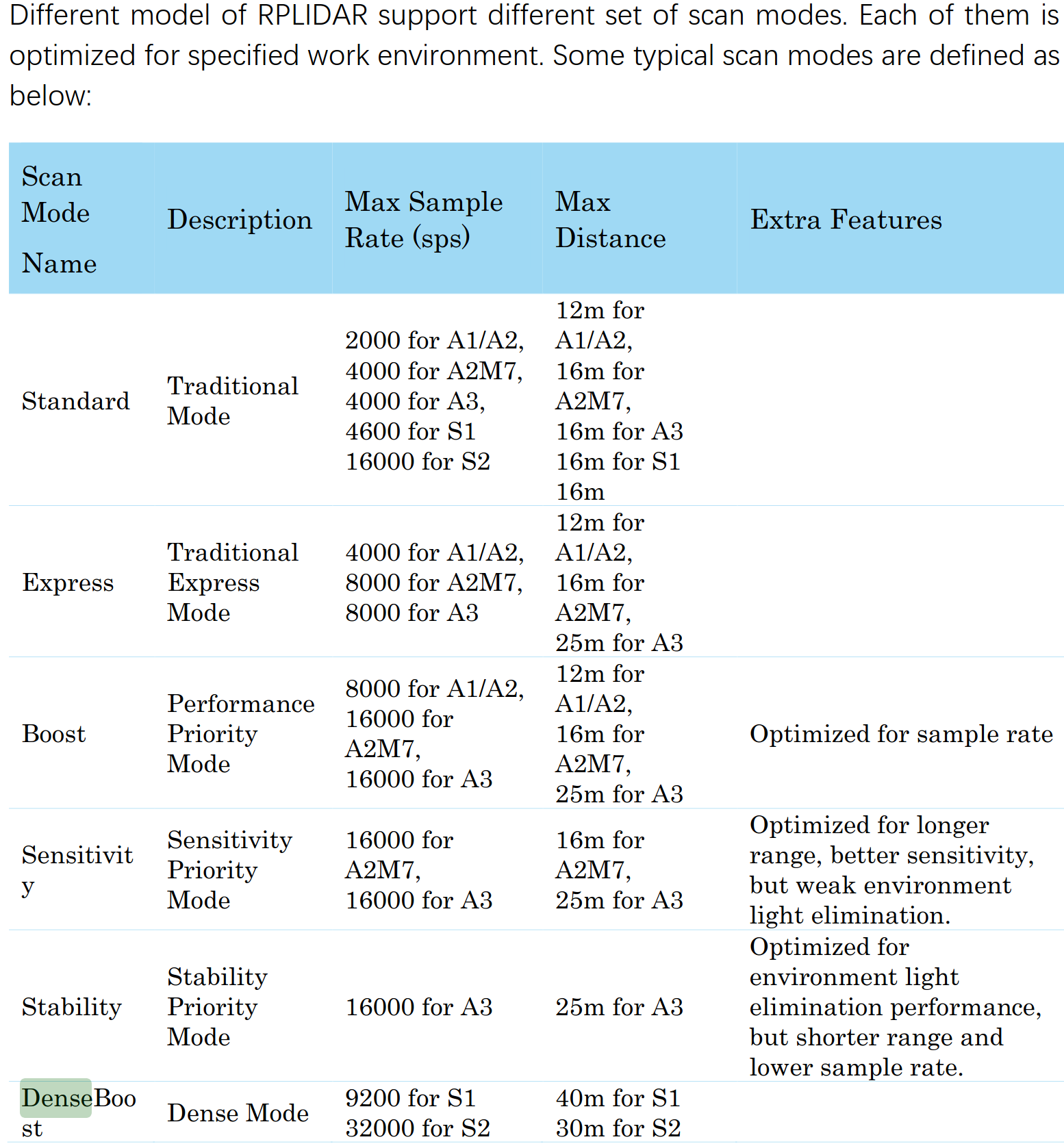
Once I managed to decipher these artifacts, I faced the real chaos: a flood of Scan Modes.
- Standard Mode: Universal but too slow for autonomous navigation.
- Express / Boost Mode: A “hack” for legacy models (A2/A3) to squeeze out more speed.
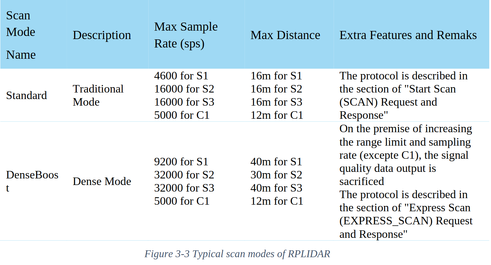
- DenseBoost (HQ Scan): The modern protocol for S-series and C1.
- Note: While S2/S3 run at a blazing 32,000 sps, the C1 uses the same protocol capped at 5,000 sps.
Crucially, the documentation for the S3 was ambiguous, sitting in a “twilight zone” between the A3 and C1 manuals. I had to perform what amounted to reverse engineering: Mapping the S3’s hardware specs onto the C1’s protocol definition (DenseBoost).
The challenge was clear: How do we melt these disparate protocol generations into a single, cohesive driver architecture?
3. The Solution: Dynamic Strategy & Auto-Detection
To hide this complexity from the ROS2 Node, I employed the Factory Pattern combined with a Strategy Pattern. But the real innovation wasn’t just the pattern—it was “Auto-Spec Detection.”
3-1. Factory with Intelligence
The user (ROS2 Node) shouldn’t care about the underlying protocol. It just demands data.
- Device Query: On initialization, the driver calls
getDeviceInfo. - Strategy Injection: The
RPLidarFactoryinstantiates the correct parser strategy:- S3, C1 Detected → Inject
RPLidarHQDriver(DenseBoost Parser) - A1, A2 Detected → Inject
RPLidarLegacyDriver(Standard Parser)
- S3, C1 Detected → Inject
3-2. Auto-Spec Detection (The “No-Hardcoding” Rule)
Instead of hardcoding specs like if (S3) max_dist = 30m, I utilized the hardware’s self-reporting capability.
“I implemented a logic using the
getAllSupportedScanModesAPI, forcing the hardware to report its own capabilities (Max Distance, Sampling Rate). This allows the driver to automatically configure itself for an S2 (30m), S3 (25m), or C1 (12m) without a single line of model-specific hardcoding.”
This transformed the codebase from a “Hardcoded Script” into an “Automated System.”
4. The Constraints: Silence and Timing
The code was logical, but the hardware has physics. My driver was initially failing with timeouts because I ignored the Timing Constraints.
4-1. The Cost of Commands
After sending a RESET or STOP command, the MCU needs time to clear its registers.
- Reality: A minimum 1ms–10ms “Cool-down” period is mandatory.
- My Mistake: Spamming commands immediately. The LiDAR ignored them, leading to a deadlock.
4-2. FSM (Finite State Machine) over sleep()
Simply adding std::this_thread::sleep_for is a band-aid solution. It blocks the thread and is non-deterministic.
I introduced a Finite State Machine (FSM) to strictly define the initialization lifecycle: CONNECTING → RESET_WAIT → WARMUP → RUNNING.
By handling the “Wait States” explicitly within the FSM, we structurally accommodate the hardware latency without blocking the entire ROS2 node. This ensures the system remains responsive even when the sensor is taking a nap.
5. Architectural Split: Wrapper vs. Node
A key design decision was the strict separation between the C++ Driver and the ROS2 Interface.
| Component | Responsibility | Tech Stack |
|---|---|---|
| RPLidarWrapper | Hardware I/O, Protocol Parsing, Threading | Pure C++17 (No ROS dependencies) |
| RPLidarNode | Lifecycle, Parameters, Pub/Sub | rclcpp, ROS2 Iron/Humble |
Why? Testability and Portability. The Wrapper can be unit-tested in isolation without a running ROS environment. If we ever need to migrate to a different middleware (or no middleware at all), the core logic remains untouched.
6. The “S3 Only” Dilemma: Crowd-Sourced Verification
Here lies the practical limitation: I am a startup engineer, not a hardware collector. I only possess an S3 unit. How do I verify the code for the A1 or A2?
(Adjusting glasses) This is where the Spirit of Open Source comes in.
I have strictly verified the S3 and HQ Protocol implementation. For the Legacy protocols (A1/A2), I implemented the logic based on the datasheets but tagged them as Untested.
“I have built the logical framework and Interface. I invite the community—those who own legacy devices—to verify this implementation and submit PRs.”
This isn’t laziness; it’s Scalability. By providing a “Dummy Driver” structure and clear Interfaces, I’ve lowered the barrier for others to contribute.
Preview: Part 4
The basic scan is working. But a driver isn’t “Production Ready” without creature comforts.
In the next and final part, we will polish the rough edges:
- Motor Control: Implementing PWM via ROS2 Services.
- Documentation: The most boring yet most important task.
- Hz Test: Final performance benchmarks.
Stay tuned.
You can check the full source code in the repository below: